Dividers corresponding waveforms latch swapped Divider 4017 yusynth sequencer schéma électronique diviseur Clock divide by 3
Programmable Clock Divider - Digital System Design
Divide by 2 clock in vhdl Counter and clock divider Clock dividers
Programmable clock divider
Divider flops frequency divide digilent waveform signalDivider clock programmable frequency clk circuit Divide clock circuit divider vhdl frequency input output eda vlsi frac cdotUse flip-flops to build a clock divider.
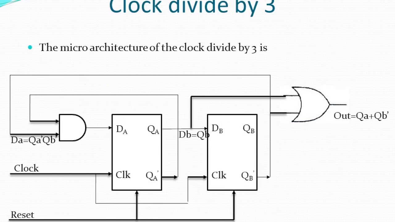
Divide digifutureClock divider tayloredge circuits pic reference source Clock dividerClock divide by 3.

Divider divide duty
Divider flop programmable digilent 8bit adder outputsHow to design a clock divide-by-3 circuit with 50% duty cycle? – digifuture Frequency division using divide-by-2 toggle flip-flopsWelcome to real digital.
Divide clock circuit cycle duty figClock 2 dividers with corresponding waveforms: (a) first and (b Clock divideFrequency using divide division flops.


Welcome to Real Digital

Programmable Clock Divider - Digital System Design

Clock 2 dividers with corresponding waveforms: (a) first and (b

CLOCK DIVIDER

How to design a clock divide-by-3 circuit with 50% duty cycle? – Digifuture

Clock divide by 3

Use Flip-flops to Build a Clock Divider - Digilent Reference
Clock divide by 3 - YouTube

Clock Dividers | SpringerLink

Divide by 2 clock in VHDL
